Generative
Design – Programmed Identity
Ulf C. Cadenbach, Henrik Hornung, Tobias O. Schelkes
Prof. Hans Dehlinger
School
of Art, University of Kassel, Germany
e-mail:
ulfcadenbach@web.de, henrikhornung@web.de, tobischelkes@web.de
Abstract
The
following article sums up three different approaches, which have been developed
by the context of the department of product design at the School
of Art of Kassel. It is about 1. reflections of the “generative approach” in
design from a student’s point of view, 2. an experiment on the identity of a
fan-like object and 3. a concept for the generative creation of a lamp shade
made of laser cut sheet metal.
All three
texts deal with the methods, the results and the created identity of generative
design. The contribution of Henrik Hornung is rather reflecting, whereas the
one of Tobias O. Schelkes is experimental and the one of Ulf C. Cadenbach deals
directly with the design of a lamp shade.
All three
contributions cover fields (theory, experiment, design), which are significant
teaching methods of the department of product design.
1. Reflections about computer generated Design
1.1 Designing and Programming
The
processes of designing and programming are quite similar concerning their
structure. Both deal with solving problems. First of all, the existing problem
is to be analysed. If the circumstances are known, the requirements for the final
product need to be defined. Now the process of designing or problem solving
begins. This requires creativity, logical thinking, imagination and experience.
Connected with the question of the realization one of the design objects is now
implemented.
A programming
language has to be learned similar to that of a foreign language, including
vocabulary, orthography, syntax and grammar. But there is one important
difference: The programming language does not accept a colloquial language. It has to be used correctly in
order to be understood. In contrast to humans the computer is not fault-tolerant.
A programme
is not built via mouse click. The instructions must be written down explicitly.
But those proceedings do not have much in common with programming yet. Although
the programme runs step by step a huge number of instructions can be written directly
into one file and implemented from there in order to visualise the result.
At the
beginning of a programme there is an idea. It relies on a thorough analysis of
what seems to be possible. And it contains the thought that the result can be
reached through a process.
By
structuring work, e.g. organisation of procedures, the idea becomes a concept.
Gradually a programme is developed, which specifies generative rules for the
computational as well as the visual implementation within the rules of the used
programming language. This is actually programming. And it has much in common
with designing.
What we
colloquially call „programming“ is defined much more precisely by computer
scientists. For them the translation of a concept into algorithms is the most
important thing.
Computer
generated design can be understood as parametric design. Apart from many
boundary conditions a certain quantity of parameters remain open. By
manipulating them one can control the total behaviour of the final design.
1.2 Calculating and Designing
A huge
asset of the computer is the generation of quantity. And this is the
theoretical condition for the generation of variety. Within a given and a
conceptually described solution space it is observed in experiments that
computer programmes generate very surprising solutions.
What is the
reason for that? The computer is ignorant. It can inevitably only do what it is
dictated. Humans however are knowing. This knowledge affects their thinking and
acting permanently in the background. From their experience humans build
connections, draw parallels, associate incessantly without the possibility of
taking distance. They possibly end up with different solutions than the
computer. But those are mostly located outside the defined solution space.
The
computer works with high speed. Where humans give up on fatigued, the computer
calculates further. Where humans stop or change the process in another
direction because they estimate the probable success as little, the computer
calculates further. This weighs particularly if a random function is integrated
into a programme. Systematically (or randomly) solutions are generated. Many of
them are possibly useless, may it be for technical or aesthetical reasons. It
can however lead to interesting surprises.
Frequently some kind of “accident” occurs while designing. Every
designer might know these situations. Many of the big inventions of mankind
have been the result of an accident. If one tries to program a solution for a
design problem it is particularly interesting to recognise such cases. One even
tries to provoke them, to cause them consciously, which is a logical paradox.
How can one plan what occurs per definition only unplanned. Designing is
however in any way and always imprisoned in such and similar paradoxes. A tiny
programming error may cause either an error message or surprise with unexpected
results. Even if such results are not directly useful, they can be inspiration
for further considerations.
1.3 The Question about Identity
Döring [1]
describes „identity“ as unmistakableness („individuality“) over the time
(„continuity“) in different situations („consistency“). Unmistakableness in the
sense of a uniqueness is not only clearly recognisable with a computer
generated design (see fig. 1.1), but always as well obviously and directly
provable on the basis of numbers. Naturally solutions are generated that
resemble each other strongly. But apart from the fact that this is the same
with “handmade” design, exactly this is a further strength of the computer.
Even if a design is already, good an appropriate programme still generates
alternatives. The closer one gets towards its aim, the more one can restrict
the computer’s scope, the more parameter settings can be fixed and the more
precise and the more defined the design becomes.
Complex
programmes are constantly tested during their developing. The designer /
programmer constantly gets direct results during this process, which he must
evaluate. Process and result are therefore subjected to a constant quality
inspection. If necessary it can be intervened at any time. And that will always
be necessary, because even if many decisions are assigned to the programme,
even if design principles are defined as algorithms, it is the substantial task
of the designer to select the best one from the multitude of results. This
requires strength of judgement, sharp thinking and a good intuition.
2
Experiment on the Identity of a Fan-like Object
2.1 Explanation of the experiment
We describe
an experiment in which we follow the question how the identity of an object can
be generated, changed or exterminated by transforming a figure. We are
structurally defining a kind of “wing” (see Fig. 2.1) which is divided into
zones. These are restricted by a value facet. We are generating two kinds of
wings by inputting these information and some random variables into a script.
(1)
angular, polygonal (see Fig. 2.2)
(2)
roundish (see Fig 2.3)
Now we are
generating objects from these wings by rotating seven elements which are
uniform around a lightly varying rotation angle (29° to °33). Being
geometrically defined the axis is always the same. The similarity to a Chinese
fan of the objects generated in this way is wanted. The identity of such a fan
is highly been determined by the kind of elements and the way it is fan-like.
There are far more characteristic items of real Chinese fans like the kind of
folding, material properties and others.
Anyway we
can prove experimentally that the „generator“, which should generate fan-like
objects really generates fan-like objects.
Based on
this initial situation we ask the following questions:
(a) What is
the identity of the generated objects? Are they invariably of fan-like kind or
appeared any new identities?
(b) Are
there any possibilities to intensify the identity?
Do
we have any possibility to generate new identities with this generator which
differs from the fan-likes?
The
generator has been programmed as Rhino Script. The conclusions are shown in the
tables 1 and 2.
2.2 Discussing
the Achievements
There is a
distinct tendency to families of forms in both the polygonal and the round kind
of objects. I divide the families by an instant overview. There are to mention
four different groups or families in this experiment. The first group contains
plane fan-like objects like result 2 and 8 of the roundish kind and 5 and 16 of
the polygonal kind. The second family includes the lightly opened like result 6
and 7 of the roundish ones and 1 and 13 of the polygonal ones. The third group contains
the more leavened forms (roundish: 1 and 3 / polygonal: 2 and 3). The fourth
group are the ones which are opened in the upper area (roundish: 4 and 11 as
polygonal: 8 and 10) and so make up the other extreme.
It is
remarkable that the identity of the objects becomes more and more another with
more openings but never loses its relationship to the fan-like kind.
By
modifying the generator to more filigree results the fan-like identity becomes
more obvious. If the modifying results in forms that are more massive in the
base area and at the same time filigree in the upper area the identity
increasingly departs from the fan-like impression.
2.3 Conclusion of the Experiment
The more
waisted and / or symmetric the generated form is the more fan-like the objects
get. Regarding the results with the number 10, 15, 14 in table 2.1 and the
results with the number 2,11,18 in table 2.2 that becomes obvious. But at the
same time there is to mention that there are borders where the conclusion
obverts and so result is less a fan-like object. Therefore the objects with the
numbers 11, 19, 23 on table 2.1 and the results with the numbers 9, 10, 19 on
table 2.2. are an example which underline this.
The
conclusion of this experiment is that by rotating a defined number of elements
around a geometrically defined rotation axis the identity becomes more and more
a different one but nevertheless still is remarkably fan-like.
3. Generation of a Lampshade from Laser cut Sheet Metal
3.1 Task
The basic idea was to design a lamp consisting of a number of sheet metal elements, which can be rotated around an axis. By using the same, but scaled shape for each element, similarities to the shell of a nautilus or pearlboat will appear.
We start with a sketched, closed curve, from which we extrude a surface. This surface is bent to a semicircular shape, copied, scaled, and rotated various times around a horizontal axis. By doing so we create a three-dimensional object.
The generative approach arised from trying to automatise iterating work processes. The shape was still sketched by hand but, to let the computer do the work of the iterating steps of copying, scaling and rotating, a small script was created for the CAD-Software Rhinoceros. Due to the fact that not every sketched shape could be processed with this one script (collisions appeared), parameters like number of elements, scale factor and rotation angle got varied and saved as stand-alone scripts. It was astonishing, which various appearances could be realised only by varying those three parameters (see fig. 3.2).
Next step was to define eight different versions of the script parameters, which represented the most characteristical appearances of the generated models (see fig. 3.1) With this “kind of generator” I tested the manually sketched shapes.
The characteristics of the models shown in fig. 3.1 could be summarised as:
- “less elements, little scale factor, large angle” versus “ many elements, large scale factor, little angle”
By using this procedure a large number of different appearances could be created, most of them were suitable for further processing. Some scripts were rejected, creating unrealisable models. For example the characteristic of “large number of elements, little scale factor (<0. 6), large rotation angle” lead to elements which were obviously too small for processing and even not visible in the model. But this helped to find out value sets for the later created generator, which almost exclusively create results suitable for processing.
In the next step a programme code was created (rhino-script), which as a generative system completely autonomous generates models of lampshades (see appendix 5.3)
This programme is fully functioning for relatively incomplex shapes. The shapes are generated by random, giving the designer or user the option to accept or decline the generated shapes for further processing (see fig. 3.4) The user also has the option to pick points by hand to create a shape and assign it to the generator for further processing (see fig. 3.3).
3.2 Operating Mode of the Generator
The generator creates eight coordinates by random. The value sets of this coordinates were chosen to avoid intersections of the generated curve. In a later version of the programme the value sets will change dynamically depending on the previous randomly created coordinates, to achieve a maximum variation of the curve.
The first and last coordinate points of the curve are located on the x-axis to get a closed shape by mirroring the curve. The following check routines make sure that the created shape is a closed curve, which is important for generating a surface and for processing the shape in a CNC lasercutter. If curve points are picked by hand, a check routine ensures that each curve point is assigned to a coordinate to avoid errors.
Now the curve is drawn, mirrored, joined and checked. A surface is now created from the emerging shape and bent semicircular.
That form is aligned parallel to the c-plane and the user is prompted to enter values for number of elements, scale factor and rotation angle. Optionally these values are generated semi-dynamically by random. From these values the CAD-Software builds the model and changes the view to perspective.
The next version will include some useful features, for example; loading of pregenerated shapes, saving of generated curves and models to files, an output of the processed values and coordinates and an option to export the shape as a .dxf-file for transferring the data directly to a CNC lasercutter (see fig. 3.6).
See fig. 3.7 for a flowchart, and appendix 5.3 for the complete program code
3.3 Conclusion
Generative design surely does not replace the classical design process. It is an interesting strategy for some concepts - like this one. In this concept a number of parameters can be varied without moving away from the basic idea.
A great advantage is to automatise iterating and tedious, but essential processes and get to significant results in a fraction of the time as compared to “handmade” models. In a given time-frame one can create and evaluate a much larger number of variations of a basic concept. Now it is possible to achieve results which in the classical design process would be declined due to lack of time.
Since the generator is deaf, dumb and blind, it will deliver concepts which the designer would never have processed nor considered due to his own preoccupation. Further on, completely new concepts arise from so called “accidents” or imprecisenesses defining parameters. These new concepts may vary from the basic idea but could be interesting by all means and lead to a completely different result.
Last but not least, it is important for students to deal with the concept of “mass customisation”, which surely show some similarities to generative / parametrical design processes.
The generative / parametrical design approach is considered a useful add-on to the classical design approaches. One should not be afraid to make use of this strategy if it seems to be useful. Consequently it is absolutely inevitable for designers to deal with this form of design approach.
4 References
[1] Döring, N.: „Sozialpsychologie des Internet. Die
Bedeutung des Internet für Kommunikationsprozesse, Identitäten, soziale
Beziehungen und Gruppen“, Hogrefe, Göttingen 1999, P. 255
Abb. 1.1: 156_curves_16_grey computergenerierte
Zeichnung, Henrik Hornung 2004
Fig. 1.1: 156_curves_16_grey computer generated
drawing, Henrik Hornung 2004
Abb. 1.2: 155_curve_16_grey, computergenerierte
Zeichnung, Henrik Hornung 2004
Fig.
1.2: 155_curves_16_grey computer generated drawing, Henrik Hornung 2004
|
|
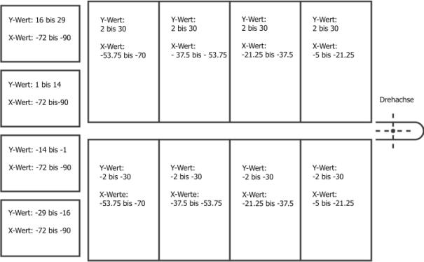
Abb.
2.1: Strukturelle Beschreibung eines Elements
Fig. 2.1: structural
description of an element


Abb.
2.2: Beispiel Outline rundlich Abb.
2.3: Beispiel Outline eckig
Fig.
2.2: example outline roundish Fig.
2.3: example outline polygonal
|
|
|
|
|
|
|
|
1 |
|
2 |
|
3 |
|
|
|
|
|
|
|
|
|
|
|
|
|
|
|
|
4 |
|
5 |
|
6 |
|
|
|
|
|
|
|
|
|
7 |
|
8 |
|
9 |
|
|
|
|
|
|
|
|
|
|
|
|
|
|
|
|
10 |
|
11 |
|
12 |
|
|
|
|
|
|
|
|
|
|
|
|
|
|
|
|
13 |
|
14 |
|
15 |
|
|
|
|
|
|
|
|
|
|
|
|
|
|
|
|
16 |
|
17 |
|
18 |
|
|
|
|
|
|
|
|
|
|
|
|
|
|
|
|
19 |
|
20 |
|
21 |
|
|
|
|
|
|
|
|
|
|
|
|
|
|
|
|
22 |
|
23 |
|
24 |
|


Tab.
2.1: Ergebnisse 7 – 24
Tab. 2.1: results 7– 24
|
|
|
|
|
|
|
|
1 |
|
2 |
|
3 |
|
|
|
|
|
|
|
|
|
|
|
|
|
|
|
|
4 |
|
5 |
|
6 |
|
|
|
|
|
|
|
|
|
|
|
|
|
|
|
|
7 |
|
8 |
|
9 |
|
|
|
|
|
|
|
|
|
|
|
|
|
|
|
|
10 |
|
11 |
|
12 |
|
|
|
|
|
|
|
|
|
|
|
|
|
|
|
|
13 |
|
14 |
|
15 |
|
|
|
|
|
|
|
|
|
|
|
|
|
|
|
|
16 |
|
17 |
|
18 |
|
|
|
|
|
|
|
|
|
|
|
|
|
|
|
|
19 |
|
20 |
|
21 |
|
|
|
|
|
|
|
|
|
|
|
|
|
|
|
|
22 |
|
23 |
|
24 |
|


Tab. 2.2: Ergebniss 1 – 24
Tab. 2.2:
results 1 – 24
|
Beispiel 1
30/15/90 |
Beispiel 2 12/15/80 |
||
|
Beispiel 3 5/15/80 |
Beispiel 4 20/15/60 |
||
|
Beispiel 5 20/45/60 |
Beispiel 6 20/45/85 |
||
|
Beispiel 7 4/80/85 |
Beispiel 8 4/60/60 |
||
|
|
|
|
|
|
|
|
|
|

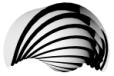


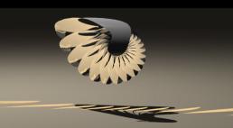

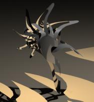
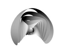
Abb. 3.2: “von
Hand” erzeugte 3D-Modelle
Fig. 3.2: “hand-crafted” 3D-models
|
|
|
|
|
|
|
|
|
|
|
|
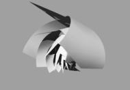
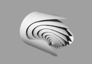
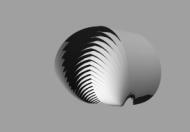

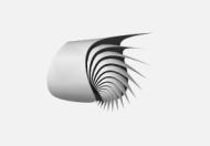

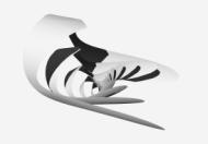
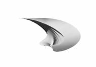

Abb. 3.3:
Lampshade Generator V3.3, parametergesteuert
Fig. 3.3: Lampshade Generator V3.3, using
parameters
|
|
|
|
|
|
|
|
|
|
|
|
|
|
|
|
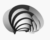
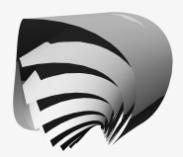
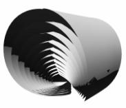
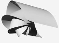
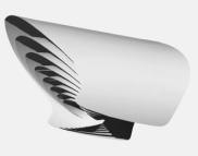
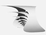


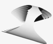
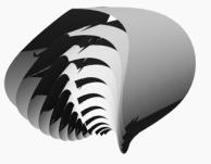
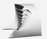
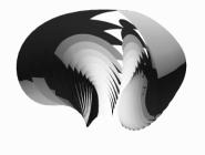
Abb. 3.4:
Lampshade Generator V3.3, zufallsgesteuert
Fig. 3.4: Lampshade Generator V3.3, randomly generated
|
|
|
|
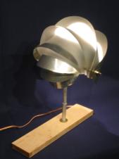
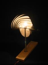
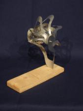
Abb. 3.5: Von
Hand erzeugte Modelle, 0.3 mm Aluminium
Fig. 3.5: handcrafted
models, 0.3 mm Aluminium
|
|
|
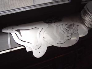
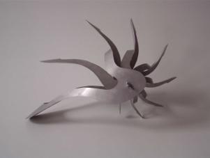
Abb. 3.6: Prototyp Edelstahl, 0,5mm CNC lasergeschnitten
Fig. 3.6: prototype stainless steel, 0,5mm CNC
lasercut
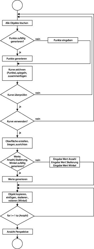
Abb. 3.7: Flussdiagramm Lampshade Generator
Fig. 3.7: flowchart Lampshade Generator